Blind & Buried Microvias for High-Density Interconnects
Advanced Via Structures for Compact, High-Performance PCB Design
Blind, buried, and laser-drilled microvia architectures enable ultra-dense HDI routing, allowing shorter signal paths, minimized vias stubs, cleaner impedance control, and higher I/O breakout under fine-pitch BGAs. At PICA, our HDI build-up processes combine laser drilling, copper filling, sequential lamination, and IPC-4761-compliant via protection to deliver reliable, miniaturized circuits for high-speed, RF, and harsh-environment electronics.
Why Choose Blind & Buried Microvias?
• Higher Routing Density – Increased trace channels and I/O breakouts through stacked/staggered microvias
• Optimized BGA Escape – Supports via-in-pad, fine-pitch BGAs, mmWave packages, and advanced HDI placement
• Superior Signal Integrity – Shorter interconnects reduce parasitics; copper-filled microvias eliminate voids and stubs
• Space & Cost Efficiency – Fewer layers with high-density build-up results in thinner, lighter, more economical boards
• Manufacturing Expertise – Requires advanced process controls: laser ablation, via fill, multi-core lamination, IPC-4761 conformance
Blind & Buried Microvias Capabilities – Highlights
Laser drilled microvias to 0.15 mm or smaller for layer to layer build up interconnects
Blind vias connecting surface layers to specific internal layers without deep penetration
Buried vias located completely within internal layers for advanced HDI routing
Stacked or staggered copper filled microvias for high reliability BGA via in pad structures
Sequential lamination and multi core build ups for advanced HDI density
Via in pad support using epoxy fill and copper cap plating aligned with IPC 4761 Type 7
Controlled aspect ratios that support reliable via plating quality
Reliability testing that includes X ray inspection, thermal cycling, cross sections, and 4 wire electrical verification
Global Design and Manufacturing Support
We engage early with your design team to define HDI stack ups, select appropriate via protection types, and optimize routing under BGA components. By aligning IPC requirements, consistent tolerances, and manufacturability from the start, we reduce risk across prototypes and full production.
Benefits of Blind and Buried Microvias
Ultra Dense Interconnects Made Practical
Microvias support diameters below 150 microns and reduce overall layer count by removing full depth drilling. This allows more routing area in less space while shrinking the total PCB footprint.
Superior Breakout Under BGAs
Via in pad combined with copper filling supports compact BGA escape and eliminates large fan out strategies. This is ideal for compact computing, wearables, RF modules, SOC packaging, and miniaturized electronics.
Improved Signal Path and RF Integrity
Copper filled microvias remove voids and reduce parasitic resistance and inductance. This benefit is critical for high speed SERDES, 5G mmWave devices, and RF communication performance.
Smaller Form Factor and Lower Layer Count
Buried and blind via strategies allow fewer overall layers while still increasing circuit density. This produces thinner devices with lower total cost and better functionality.
Reliable Manufacturing for Volume Production
Controlled laser drilling, resin or copper filling, lamination cycles, and IPC qualified sealing strategies provide repeatable HDI reliability across early prototypes and full scale production.
Markets We Serve with Blind and Buried Microvias
Mobile and Consumer Electronics
Miniaturized HDI designs for foldable devices, SOCs, compact RF modules, and camera subsystems.
Medical Devices
Implantable sensors, wearable monitoring platforms, and high pin count microelectronics where reliability and miniaturization are critical.
Automotive and Transportation
HDI boards in harsh vibration and thermal environments that require strong mechanical support for blind and buried vias.
Telecommunications and 5G Infrastructure
mmWave modules, routers, switching blades, and RF signal processing platforms that require clean impedance transitions.
Industrial and Defense Electronics
Satellite systems, flight computers, drones, and space restricted computing modules where rugged density is essential.
All too often Printed Circuit boards are viewed as simple two-dimensional surfaces. Nowhere is this oversimplification more evident than in the complex structure of Vias. These essential structures are critical to the form and function of any PCB with more than a single layer. Without these vias modern electronics would not be possible in the way we know them today. This paper delves into the importance of via protection, what the Institute for Printed Circuits (IPC) recommends, the types of via protection, their applications, and the inherent limitations and trade-offs.
Printed Circuit Boards (PCBs) form the backbone of modern electronic devices, providing the physical platform for mounting and interconnecting electronic components. Among the essential elements in PCB design are vias—small holes that allow electrical connections between different layers of the board. Vias play a role in ensuring efficient routing of electrical signals, managing thermal performance, and optimizing space within complex multi-layer boards.
The blogs featured below expand on this page’s content, offering detailed insights into specific design, manufacturing, and application topics that provide added relevance and deeper context for engineers and decision-makers.
PCB, Flex & PCBA Cost Pressures in 2026: What OEMs Need to Watch
Electronics manufacturing is heading into 2026 under pressure from several directions at once. Rising metals costs, laminate and prepreg repricing,...
Integrated Flex Circuits and Injection Molding for Electronic Devices
At PICA Manufacturing Solutions, we believe the future of electronics is not built component by component, it is engineered as...
How Flex PCBs Are Shielded for EMI and RFI Protection
Electromagnetic interference (EMI) and radio frequency interference (RFI) can disrupt signal quality, create data errors, and reduce...
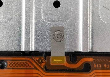
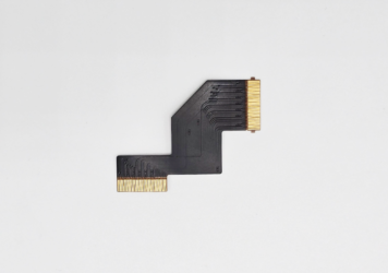
Nickel Tab Mounting on Flex Circuits: Strengthening Electrical and Mechanical Connections
Flexible circuits are often chosen for their ability to route signals through tight spaces while tolerating bending...
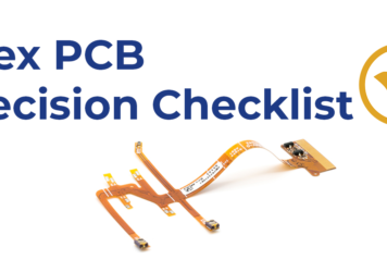
Material Selection Framework for Flex PCBs
A practical step-by-step method for choosing materials that hold up in bending, assembly, and real environmentsFlex material...
Alternatives to Copper in Flexible Circuits
Copper has been the backbone of flexible printed circuits (FPCs) for decades, and for good reasons. While...
Auxiliary Materials in Flex PCB Builds
Stiffener, EMI Shielding, Release liners, spacers, marking inks, thermally conductive adhesive films, and PSA selection guidance.When engineers...
Designing PCBs for Medical Devices: Key Considerations & Compliance Tips
PCB design for medical electronics demands more than just electrical functionality. Devices must meet...


