Electrical Verification Protocols: Preliminary Testing of Unpopulated Circuit Boards
Simon Lim2025-07-23T17:52:02+00:00Welcome to our two-part blog series on Electrical Verification Protocols at PICA Manufacturing Solutions. Ensuring the quality and reliability of our printed circuit boards (PCBs) and flexible printed circuits (FPCs) is paramount. This series delves into our rigorous verification processes, starting from the preliminary testing of unpopulated circuit boards, followed by functional testing of complete circuit assemblies. These protocols illustrate our commitment to maintaining excellence in manufacturing while meeting both industry standards and customer expectations.
Preliminary Testing of Unpopulated Circuit Boards
Introduction
In the first part of our series, we explore the foundational steps of our electrical verification process, focusing on the testing of circuitry before components are added. This stage is crucial for identifying potential issues early in the production cycle, ensuring that the circuit integrity is maintained from design to delivery.
- Preparation: Design Review and Test Plan Development
Before any physical testing begins, a crucial preparation phase ensures that all subsequent activities are aligned with the PCB and FPC specifications and customer expectations.
Design Review
The first step involves a thorough review of the PCB design files, including schematics and layout. This review helps us understand the expected electrical behavior and identify potential issues that could impact performance.
Test Plan Development
Based on the design review, we develop a comprehensive test plan that outlines the specific tests to be performed, the equipment needed, and the acceptance criteria. This plan ensures that every aspect of the PCB’s functionality and performance is verified before it reaches the customer.
- Visual and Automated Optical Inspection (AOI)
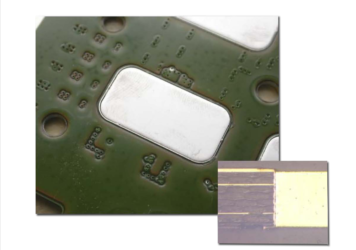
Before diving into the electrical tests, every PCB and FPC undergoes a thorough visual inspection to check for any physical defects, such as solder bridges, missing components, or incorrect placements. This crucial first step helps prevent basic errors from affecting the subsequent testing phases.
Inspection Techniques
Manual Inspection: Our technicians perform a detailed manual check to identify any visible defects that might compromise the PCB’s functionality.
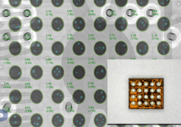
Automated Optical Inspection (AOI): We employ advanced AOI technology that scans the PCBs with high-resolution cameras to detect finer defects like thin solder bridges or minute misalignments not easily visible to the human eye.
- Continuity and Short Circuit Testing
Continuity and short circuit testing is crucial for verifying both the integrity of conductive paths and the absence of unintended shorts in PCBs and FPCs. This ensures that the electrical connections are correct and there are no faults that could lead to component failures or operational issues once the circuit is fully populated.
Test Methodology
For these tests, a typical setup involves applying a small DC voltage (about 5 to 10 volts) and a current (usually around 10 to 100 milliamperes). This setup effectively detects any discontinuities or unintended shorts without damaging the delicate circuitry. In scenarios requiring high precision, such as those with very tight circuit layouts, we may use a four-wire (Kelvin) measurement technique. This method enhances accuracy by eliminating the influence of test lead and contact resistances, providing a more reliable verification of the PCB or FPC’s electrical integrity.
Did you enjoy reading this blog? Click below to read part 2 Electrical Verification Protocols: Functional Testing of Complete Circuit Assemblies.

- Insulation Resistance Testing
Insulation resistance testing is indispensable, especially in environments where electrical components are exposed to high voltages. This test helps prevent dangerous leakage currents that can cause operational failures and safety hazards.
Test Methods and Applications
We conduct insulation resistance tests using a megohmmeter that applies a specified high DC voltage—commonly 100V, 250V, 500V, or 1000V—depending on the application requirements and the insulation type. The resistance is expected to be in the megaohms range, typically from 10 MΩ to several GΩ, which indicates good insulation properties. This test is critical for detecting any degradation or flaws in the PCB materials or manufacturing process, such as contaminants or micro-cracks that can compromise the circuit’s safety and functionality.
- Impedance Testing
Maintaining controlled impedance in bare circuits is critical, particularly for high-frequency PCBs where signal integrity is crucial. In this stage of testing, we measure the impedance of circuit paths before components are mounted to ensure they match the designed specifications.
Understanding and Testing Impedance
Impedance testing measures the resistance to the flow of alternating current (AC), which includes both resistance and reactance at a specific frequency. This test is essential for high-frequency circuits where mismatches in impedance can lead to signal reflection, distortion, and loss, compromising the performance of the final product.
Testing Methodology
We typically employ a network analyzer to conduct impedance tests on bare circuits. The analyzer sends a small AC signal through the circuit paths and measures the resulting impedance at various frequencies. The results are compared against the target impedance values specified in the design documents. These values must be tightly controlled, usually within a few percent of the target, to ensure the circuit will function as intended once components are mounted and the device is
Conclusion
Concluding our examination of circuitry testing before component assembly, we underscore the importance of rigorous testing of unpopulated boards. Stay tuned for Part #2, where we will delve into the comprehensive testing of circuitry with mounted components, further ensuring that each assembly operates flawlessly in its intended application.


