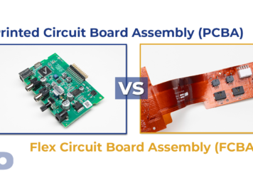
Bending Without Breaking: How Flexible Circuits Are Tested for Reliability
Eric Zhao2025-08-05T13:18:41+00:00Flexible circuits are built to bend—but only when designed and tested to handle real-world mechanical demands. Whether your product is a wearable device, medical catheter, or automotive sensor, the reliability of a flex circuit under repeated bending, twisting, or flexing is critical to its success.
At PICA Manufacturing Solutions, we rigorously test flexible and rigid-flex circuits to meet the mechanical durability and electrical performance our customers—and their products—demand.
Why Flex Circuit Reliability Testing Matters
While flexibility is the core advantage of FPCs, every application has different expectations for how, when, and how often the circuit will flex. That’s why testing is never one-size-fits-all.
Without proper validation:
• Traces may crack over repeated cycles
• Dielectrics can delaminate or fatigue
• Signal integrity may degrade over time
• The final product could fail in the field
Our approach is to simulate and test real-use conditions to ensure flex circuits are functionally and mechanically reliable—not just out of the box, but after thousands of operations.
Key Reliability Tests for Flexible Circuits
PICA’s flex circuit testing protocols are tailored based on customer requirements, industry standards (like IPC-2223, IPC-6013), and product-specific risks. Common tests include:
1. Dynamic Flex (Bend Cycle) Testing
Simulates repeated bending around a defined radius. Circuits are flexed 10,000+ times to measure durability.
• Used for: Wearables, folding electronics, robotic systems
• Goal: Ensure copper and adhesive integrity during lifetime movement
2. Flexural Endurance Testing
Simulating the peel force test in actual use scenarios to verify whether the FPC will have adhesive failure during transportation, installation or long-term use.
• Used for: Flexible material selection, all FPC applications
• Goal: Mainly test the fatigue resistance of materials under cyclic bending loads, determines the number of cycles or stress levels they can withstand, and is often used to evaluate the reliability of engineering materials.
3. Peel strength testing
Simulate the mechanical behavior of materials during repeated bending processes to determine their fatigue or durability limits.
• Used for: Smartphones, Wearables
• Goal: Evaluate the bond strength between a conductive layer (such as copper foil) and a substrate (such as polyimide or polyester) to predict the risk of delamination during manufacturing and use of the product to ensure its reliability and service life
4. Thermal Cycling
Test how materials handle temperature extremes and rapid transitions.
• Used for: Automotive, aerospace, industrial applications
• Goal: Evaluate solder joint reliability, material expansion, and shrinkage effects
5. Heat Resistance Testing
Simulate a high temperature environment (such as 288±5°C tin furnace) to evaluate the ability of FPC to withstand high temperatures in a short period of time (usually 10 seconds)
• Used for: All FPC applications
• Goal: Verify the stability of the circuit board in a high temperature environment to avoid quality problems such as board explosion, blistering and delamination caused by high temperature.
6. High Temperature/Humidity Testing (85/85)
Exposes circuits to 85°C at 85% humidity for extended periods.
• Used for: Medical devices, outdoor sensors
• Goal: Identify risk of delamination, corrosion, and dielectric degradation
7. Electrical Continuity Testing
Ensures that signals pass consistently before, during, and after mechanical stress.
• Used for: All FPC designs
• Goal: Verify trace integrity and connection stability over time
8. Optical & X-ray Inspection
Used to detect internal cracks, solder joint voids, and structural fatigue after mechanical tests.
• Used for: Complex rigid-flex or fine-pitch assemblies
• Goal: Spot early signs of wear or latent failure points
Ensure Your Flex Circuits Stand the Test
of Time
Partner with PICA to design, validate, and manufacture flexible circuits built for real-world durability.
Custom Test Protocols Based on Application Needs
Every product has its own performance envelope. That’s why PICA collaborates with you to define test parameters that reflect your real-world use case, including:
• Bend radius and angle
• Flex frequency and lifetime cycles
• Twisting or torsional motion
• Environmental exposures (moisture, vibration, heat)
• Electrical impedance
• High potential testing or Dialectic withstanding testing
• Leak Tests
• Salt spray test
• Ionic contamination test
Peel strength test
High Temperature and humidity chamber
Thermal Shock chamber
Impedance test
We match your mechanical demands with the right materials, adhesives, reinforcement, and fabrication techniques—and back it up with proven test data.
Industries That Can’t Compromise on Flex Reliability
Flex circuit reliability testing is especially critical in industries where safety, performance, or uptime can’t be left to chance:
1. Medical
• Surgical and diagnostic devices with dynamic movement
• Patient-worn monitoring systems
• Need high confidence in bio-compatibility and continuous operation
2. Automotive
• Engine control units, sensors, and lighting systems in hot, vibrating environments
• Flex circuits must endure thousands of flex and thermal cycles
3. Aerospace & Defense
• Navigation and control systems exposed to vibration and altitude changes
• Critical data must flow uninterrupted through rugged flex interconnects
4. Consumer Electronics
• Folding phones, smartwatches, and wearables that flex constantly
• Requires compact design and long-lasting durability
5. Industrial Automation & Robotics
• Dynamic cable systems and sensor arrays that move with machinery
• Must withstand high duty cycles in harsh environments
PICA’s Reliability-First Approach
At PICA, our process begins with Design for Reliability (DFR) and continues through to custom testing and final validation:
• Design Input: We ask the right questions to define your bending and environmental expectations
• Material Selection: Choose adhesives, polyimide thicknesses, and copper weights suited to your flex cycles
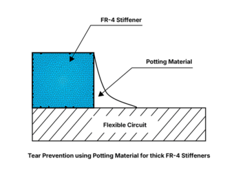
• Stack-Up Engineering: Optimize the placement of stiffeners, ground planes, and unsupported areas
• Prototype Validation: Real-world testing—bending, heating, and stressing—to make sure it lasts
• Scalable Production: Consistent quality and inspection at scale, with test data to back it up
Whether you need a 2-layer dynamic flex circuit or a 10-layer rigid-flex with embedded passives, we ensure your design can handle the wear and tear of reality—not just the prototype bench.
Do you have specific reliability or bend requirements for your flex circuit? We can build a custom test plan to match your product’s environment and performance goals.
Talk to PICA’s engineering team to get started with design reviews, test protocols, and prototype evaluation.