Optimizing Design for Flexible Circuits Part 2: Advanced Design Strategies for Flexible Circuits
FlexPros2025-07-24T15:36:10+00:00In the continuation of our series on optimizing flexible circuit designs, we delve into additional critical aspects that ensure functionality and durability in challenging environments. PICA Manufacturing Solutions brings you expert insights into managing mechanical stresses and enhancing the robustness of your flexible circuits.
Strain Relief
When integrating thick FR4 stiffeners, consider the application of potting material between the FR4 and the flex circuit. This method acts as a cushion, providing strain relief during bending, thereby enhancing the circuit’s durability and flexibility in dynamic applications.
Tear Resistance
To increase tear resistance, certain design features can be incorporated:
- Large Radii in Corners: Prevents stress concentration which can lead to tearing.
- Embedded Glass Cloth: Provides structural integrity and resistance to tearing.
- Recessed Slot and Hole in Slit: Reduces the likelihood of tear initiation.
- Drilled Hole at Corner: Disperses stress that can cause tears at vulnerable points.
- Embedded Aramid Fiber: Offers high strength and resistance to tearing.
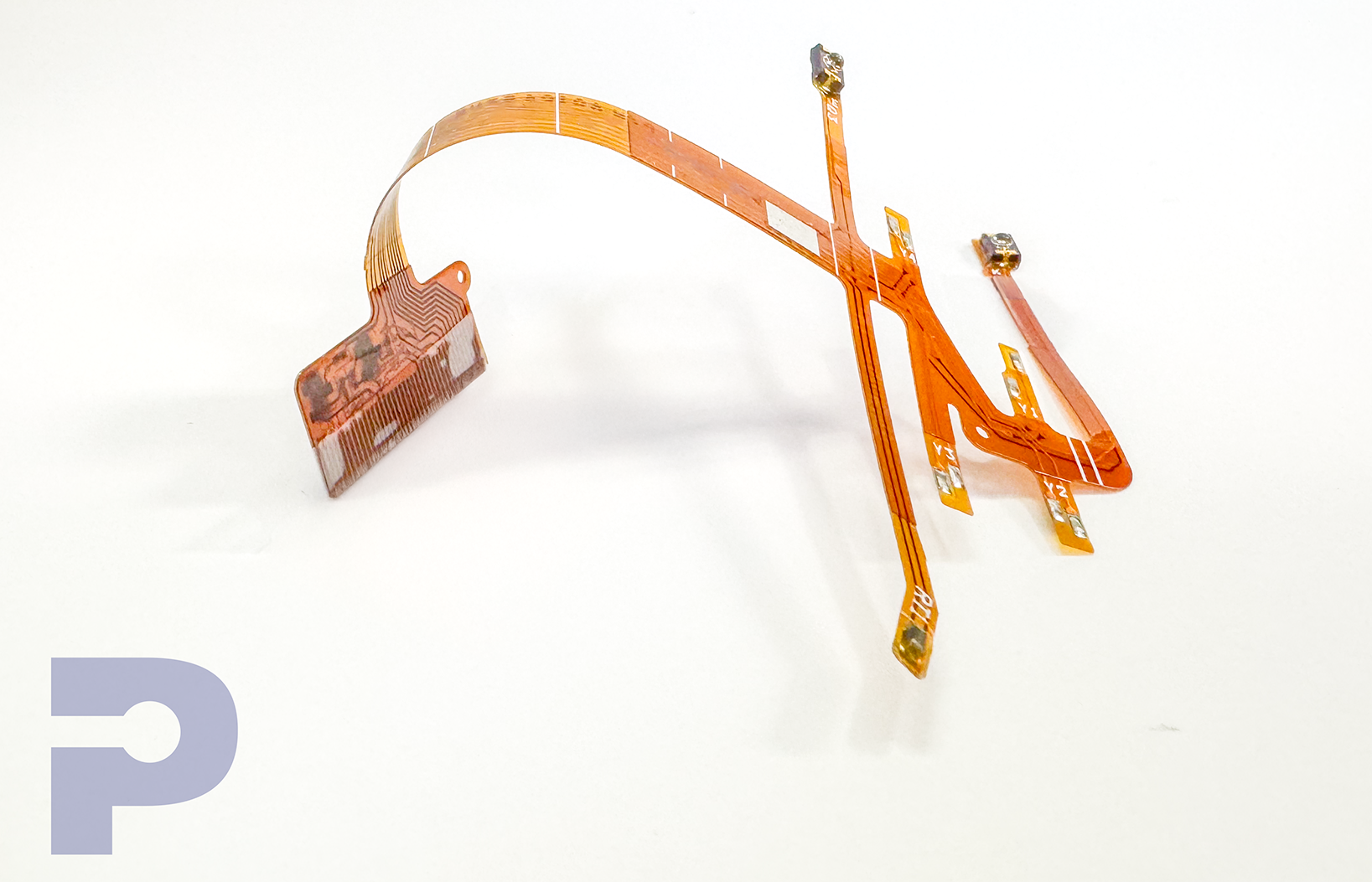
- Extra Copper in Corners: Strengthens corner areas which are prone to higher stress.
Vibration and Shock
In environments subject to high vibration and shock, securing the flex circuit is paramount. Utilizing mounting hardware such as fasteners, clamping devices, screws, clips, and relief bars helps minimize movement. Additionally, incorporating mounting holes into the flex circuit design can prevent tearing by stabilizing the circuit within its assembly.
Filleting Pads and Conductor Routing
Filleting pads at the junctions of circuit lands and conductors help distribute stress more evenly, improving circuit reliability. Avoiding sharp corners in trace routing is also advisable—opt for smooth transitions with radii to reduce stress concentrations known as stress risers.
Tolerance Setting
For precise assembly and measurement, the use of multiple fiducials is recommended. Designating one as the prime and others as secondary aids in maintaining accuracy throughout the manufacturing process, ensuring components are placed correctly relative to the flex circuit.
Ground Planes
To enhance the flexibility of the circuit, consider crosshatching ground planes. Additionally, ensure ground connections are thermally relieved to mitigate heat sinking effects during the soldering process, which can otherwise lead to damage or weakened joints.
Start Your Project Today!
Contact us today to schedule an appointment to speak with a PICA Manufacturing Solutions engineer today. We look forward to hearing about your project!
Unsupported Mounting Holes
For flex circuits that will be mounted without mechanical backing, ensure mounting holes retain their copper. This measure provides additional structural support and reduces the risk of tear around these critical points.
Bending Flex Circuits to Hold Shape
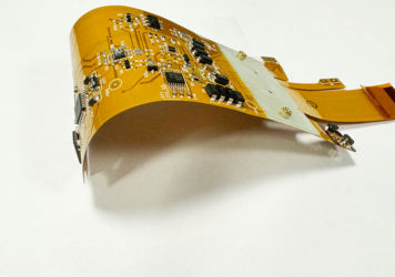
Creating a permanent bend in flexible printed circuits (FPCs) can be achieved by widening copper traces through the bend area, using thicker copper, or applying heat forming techniques. These modifications help maintain the desired shape and functionality even under repeated use.
Minimizing Material Waste through Optimized Nesting
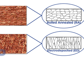
For flex circuits with odd shapes, it is crucial to nest these within a panel efficiently to minimize material waste. The optimized nesting may also depend on the copper grain direction on a given piece of copper foil. For some dynamic applications, it is essential that the conductors in the flexing areas are positioned parallel to the grain direction of the RA copper foil, improving fatigue life. Additionally, if folds are utilized to further improve nesting, the designer should carefully consider the orientation of access pads before and after folding. This approach not only conserves materials but also aligns with sustainable manufacturing practices.
By incorporating these advanced design strategies into your flexible circuits, you can significantly enhance their performance and durability. Stay tuned for more insights from PICA Manufacturing Solutions as we continue to lead the way in innovative circuit design and engineering excellence.
Contact us with any questions on flexible printed circuit boards.
