Metal Core PCBs (MCPCBs): Thermal Muscle for High-Power Electronics
Ellen Wang2025-10-21T18:43:17+00:00Modern electronics pack more power into tighter spaces than ever. That heat has to go somewhere. Metal Core Printed Circuit Boards (MCPCBs) solve the problem at its source by building a heat-spreading layer directly into the board. PICA Manufacturing Solutions designs and manufactures aluminum- and copper-core MCPCBs—single-layer, multi-layer, and hybrid assemblies—engineered to your thermal, electrical, and mechanical requirements.
Why Metal Core Instead of FR-4?
Compared to traditional FR-4 boards, MCPCBs offer:
• Efficient heat dissipation. The metal core acts like a built-in heat sink, flattening hot spots and lowering junction temperatures.
• Improved reliability. Cooler components = less solder fatigue, fewer thermal cycles on materials, longer service life.
• Higher power density. Better heat flow enables more LEDs, MOSFETs, drivers, and regulators in the same footprint.
• Stronger mechanics. Stiffer substrates improve robustness in shock/vibration and simplify heat-sink attachment.
• Better CTE control. Tailored expansion behavior reduces stress on components during temperature swings.
When to choose MCPCB: high-power LEDs and light engines, motor drives and power conversion, RF power stages, braking/actuation modules, or any design where thermal margins bottleneck performance.
Core Use Cases & Markets
• LED lighting & light engines: COB modules, light bars, backlights, horticulture, UV curing—white solder mask and high reflectivity options.
• Power electronics: DC-DC/AC-DC conversion, motor/BLDC drives, inverters, e-mobility chargers, battery management.
• Automotive & transportation: Headlamps/taillights, ADAS illuminators, under-hood power modules, signaling.
• Industrial & robotics: High-current drivers, actuators, solid-state relays, high-brightness indicators.
• Communications & RF power: PAs and LNAs that run hot, small form-factor base station modules.
• Medical & instrumentation: Illumination engines, analyzers, imaging light sources where stable output and long life matter.
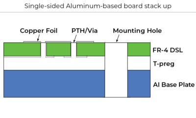
MCPCB Stackups—What’s Inside
A typical insulated metal substrate (IMS) stack is:
1. Metal core (Aluminum or Copper)
• Aluminum: the value leader—excellent thermal conductivity, good weight, easy machining.
• Copper: maximum heat spreading and stiffness; ideal for extreme power density.
2. Thermally conductive dielectric
• Electrically insulative; high thermal conductivity (measured in W/m·K) and thin to reduce thermal resistance.
• Formulated for breakdown voltage, thermal cycling endurance, and adhesion.
3. Copper circuit layer
• Etched traces, pads, and copper pours. Heavy copper options for high current.
• Solder mask and surface finishsurface finish (e.g., ENIG, OSP, ImmAg) selected for assembly needs.
Single-layer MCPCB is the workhorse for LED and power stages.
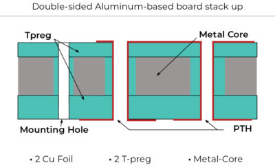
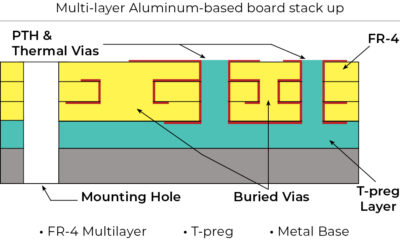
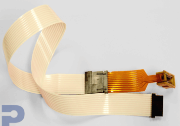
Multi-layer MCPCB options exist (e.g., 2L with buried interconnects, or hybrid laminations), but through-holes cannot pass through the metal core—interconnect is achieved via local build-ups, island sub-assemblies, or hybrid bonding. For complex logic + thermal zones, we often recommend hybrid designs (MCPCB for the hot zone + FR-4/rigid-flex for control) joined by flex/FFC—the best performance per zone without fighting physics.
Ready to eliminate thermal bottlenecks?
Contact PICA today to discuss your MCPCB design and production needs.
Manufacturing Considerations (What to Plan Up Front)
Material & dielectric selection
• Target thermal conductivity and dielectric thickness based on allowable ΔT from junction to board backside.
• Validate breakdown voltage for your creepage/clearance needs.
Copper & current handling
• Choose copper weight for IR drop and temperature rise; consider heavy copper and wide pours for hot paths.
• Use thermal spokes judiciously to balance solderability with heat flow.
Plated features & interconnect
• Standard vias cannot go through the metal core. For multi-layer needs, plan local FR-4 buildups, microvias, or hybrid MCPCB+FR-4 assemblies.
• For high-current jumpers, evaluate press-fit pins, eyelets, or bus bars.
Board outline & machining
• MCPCBs are routed, punched, or laser-processed with metal-safe clearances.
• Define keep-outs near edges, chamfers for heat-sink fit, and countersinks for fasteners.
Surface finish & mask
• ENIG and ImmAg are common for LED pads and fine-pitch parts.
• White solder mask boosts optical output for lighting; black for stray light control; matte options for glare.
Assembly profile
• The metal core increases thermal mass; tune reflow profiles and stencil apertures to ensure proper wetting without overheating smaller passives.
• Plan thermal interface material (TIM) between the MCPCB backside and chassis/heat sink (pad, phase-change, or grease).
Test & compliance
• Define powered thermal tests (steady-state temp, ramp/soak cycling) and electrical safety checks (hipot across dielectric).
• Align to required standards and documentation (e.g., RoHS/REACH, UL marking, IPC class targets).
Design Tips for Better Thermal & SI Results
• Short, wide paths from hot components to copper pours; minimize thermal bottlenecks.
• Place thermal vias in local FR-4 buildups (not through the metal) to spread heat within the copper layer when needed.
• Use copper coins or slug-in techniques in specialty cases where direct heat paths are required (project-specific feasibility).
• For switching power and RF, plan return current carefully—reserve ground copper around hot loops to control EMI while maintaining heat spread.
• Model early: simple θJA/θJB estimates, then CFD if margins are tight.
MCPCBs let you push power and reliability without expanding your enclosure or bolting on exotic heat sinks everywhere. Whether you need a straightforward aluminum IMS for a light engine or a hybrid copper-core module tied to FR-4 control logic via flex, PICA will help you select materials, validate thermals, and build for scale.
Ready to de-risk your thermal stack?
Share your target power, temperatures, outline, and mechanical constraints. We’ll propose an MCPCB (or hybrid) that meets your performance, cost, and schedule—then take it from prototype to production.
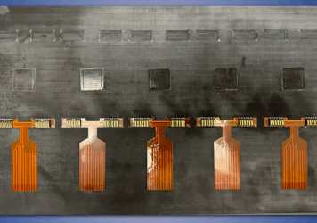
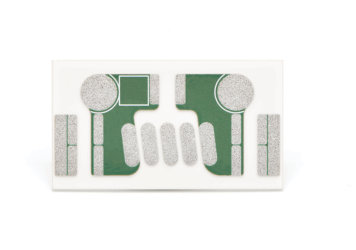
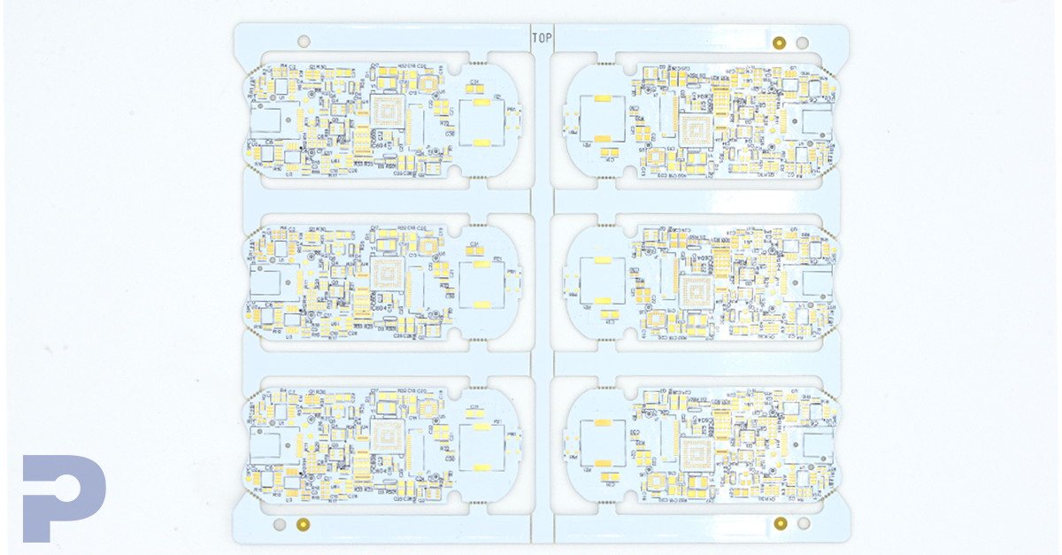
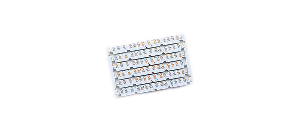
Various Metal-based board stack up