
Essential Documentation and Data Files for PCB Component Assembly
FlexPros2025-09-02T13:11:36+00:00When ordering component assembly for your Printed Circuit Boards (PCBs) and Flexible Printed Circuits (FPCs), it’s important to provide the right documentation and data files to ensure accurate and efficient assembly. Below, we outline the mandatory files and information needed, as well as additional items that are good to have for an optimized assembly process.
Mandatory Documentation and Files
- CAD Files
Description: CAD files provide detailed 2D or 3D models of the PCB and its components. They offer a complete visual representation, helping us understand the exact design specifications and component placements, which are critical for both design verification and assembly accuracy.
- Gerber Files
Description: Gerber files detail the physical layout of the PCB, including copper layers, solder mask, and silkscreen. These files are essential for manufacturing the PCB layers accurately and ensuring the physical structure matches the design.
- Bill of Materials (BOM)
Description: A BOM is a comprehensive list of all components required for the PCB assembly, including part numbers, descriptions, quantities, and supplier information. The BOM ensures that the correct components are ordered and used during assembly, preventing costly errors and delays.
- Pick and Place Files
Description: These files provide the exact coordinates for placing components on the PCB during automated assembly. Accurate pick and place files are crucial for automated machines to place components correctly, ensuring high precision and reliability.
- Solder Paste Files
Description: Solder paste files detail the application of solder paste on the PCB, including specific locations and volumes. Correct solder paste application is critical for ensuring strong and reliable solder joints.
- Assembly Drawings and Schematics
Description: Assembly drawings show component placement, while schematics provide a detailed circuit diagram. These visual aids help verify component placement and electrical connections, ensuring the assembly meets design specifications.
Start Your Project Today!
Contact us to schedule an appointment with a PICA engineer about your project. We look forward to hearing from you!

Good to Have Documentation and Files
- Mechanical Drawings
Description: Mechanical drawings provide detailed dimensions and specifications for the physical aspects of the PCB and its enclosure. These drawings help ensure that the PCB fits within its intended enclosure and meets all mechanical requirements.
- Netlist Files
Description: Netlist files list all electrical connections on the PCB, detailing which pins on components are connected. They are used to verify that the PCB layout matches the intended electrical design.
- Definition and Placement of Fiducials
Description: Fiducials are reference marks on the PCB that serve as alignment aids during manufacturing. Proper fiducials ensure accurate component placement and alignment during assembly.
- Assembly Process Instructions
Description: These guidelines outline the procedures for assembling the PCB, covering all stages, including component placement and soldering. Clear instructions help ensure consistency and quality across the assembly process.
- Functional Test Procedures and Fixtures
Description: These procedures describe the steps to test the functionality of the PCB, while fixtures are tools used to facilitate these tests. Functional testing ensures that the PCB performs as expected, identifying any issues before deployment.
- In-Circuit Testing (ICT) Requirements
Description: ICT involves using test probes to access test points on the PCB, checking for component presence, orientation, and electrical continuity. ICT provides a thorough check of the PCB’s assembly quality without powering up the board, helping catch issues early.
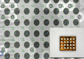
- X-ray Inspection Requirements
Description: X-ray inspection identifies defects like voids and misalignments in hidden solder joints. This inspection helps ensure solder joints are free of defects that could compromise reliability.
- Regulatory and Compliance Information
Description: This includes information on RoHS compliance, REACH compliance, conflict minerals reporting, IPC standards, and other industry-specific regulatory requirements. Compliance ensures that your PCBs meet legal and industry standards, avoiding potential penalties and market restrictions.
- Golden Sample
Description: A golden sample is a reference unit representing the highest quality and correct version of an assembled PCB. It serves as a benchmark for quality control and comparison during production.
- Statement of Work (SOW)
Description: The SOW is a formal document defining the scope of work, project objectives, and criteria for success, serving as a contract between you and PICA. It ensures clear communication and agreement on project expectations and deliverables.
By providing these mandatory files and including good-to-have items, you help PICA deliver the highest quality PCB assemblies, tailored to your specific needs and requirements. If you have any questions or need assistance in preparing your documentation, please feel free to contact our team.