Designing for Precision: Controlled Impedance in Flexible Circuits
Precision Manufacturing & Testing at PICA
Controlling impedance requires more than just good design. Manufacturing must be equally precise:
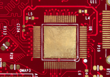
• Optimal Etch Compensation: Ensuring trace widths and spacing
• Tightly Controlled Lamination: Ensuring uniform dielectric spacing
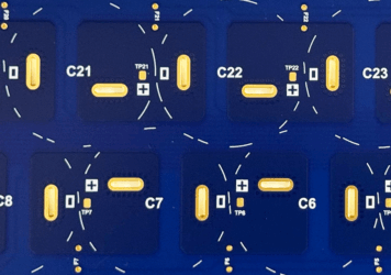
• Advanced AOI (Automated Optical Inspection): Verifies trace widths and spacing
• TDR (Time Domain Reflectometry): Validates impedance performance before shipment.


Our engineering and quality teams work closely with you to ensure your impedance targets are met from concept to completion.
Where Controlled Impedance in Flex Circuits Makes the Biggest Impact
Controlled impedance isn’t just a design preference—it’s essential for reliable performance in today’s high-speed, space-constrained electronics. At PICA, we support industries where signal clarity is non-negotiable:
Medical Devices
• Wearable patient monitors
• Imaging probes and catheters
• Implantable telemetry systems
These applications demand small form factors with precise signal performance, often under dynamic movement or heat.
Aerospace & Defense
• Avionics and navigation systems
• Rugged sensor networks
• Tactical communication equipment
Controlled impedance ensures mission-critical signals are clear, fast, and immune to interference in harsh environments.
Automotive & EV Systems
• Radar and camera systems
• In-vehicle infotainment and data buses
• Battery management and power delivery
Modern vehicles use high-speed digital interfaces and FPCs to reduce weight while maintaining performance under vibration and temperature swings.
Consumer Electronics & IoT
• Smartphones and tablets
• Smartwatches and fitness bands
• Connected home and industrial IoT
Flex circuits allow compact, curved form factors with tightly packed signal paths—requiring careful impedance control to prevent crosstalk and signal loss.
Industrial & Robotics
• Automated inspection systems
• Machine vision
• Factory sensor networks
Flexibility and durability are key in moving or rotating equipment, but signal reliability cannot be compromised.
Why Engineers Choose PICA for Controlled Impedance Flex Circuits
At PICA, we provide:
• Full-stack expertise – From DFM reviews to stack-up modeling
• Precision processes – Tight material and etching tolerances
• Advanced inspection – TDR, AOI, and impedance validation
• Flexibility-focused engineering – Designs that bend, but don’t break signal performance
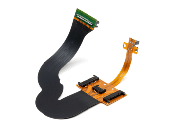
Whether you need a single-ended flex circuit or a multilayer rigid-flex with differential pairs, we partner with you to deliver signal consistency and mechanical reliability in every build.
Ready to Control Your Signals?
Let’s talk about your next high-speed flex or rigid-flex project. Our engineers are ready to review your design and help optimize it for performance, manufacturability, and cost.