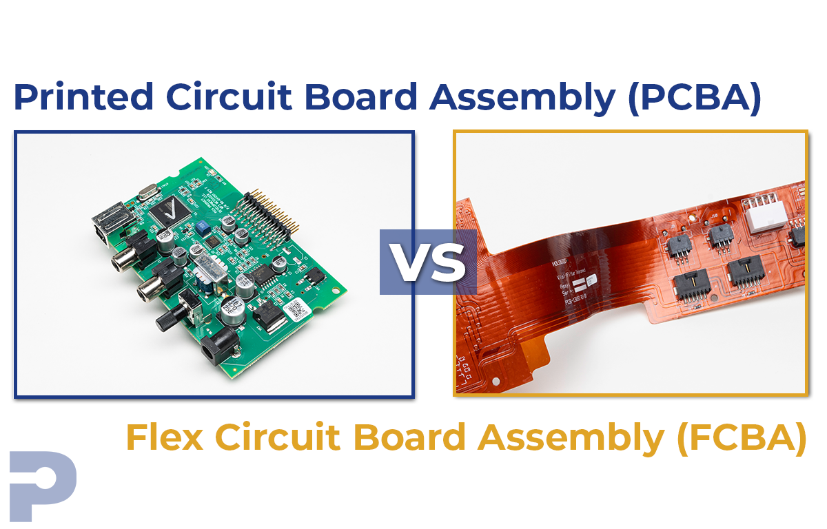
PCBAs vs. FPCAs: Understanding the Differences
Simon Lim2026-03-11T18:18:42+00:00PCBAs (Printed Circuit Board Assemblies) and FPCAs (Flexible Printed Circuit Assemblies) are both integral to the functioning of electronic devices, yet they cater to distinct needs due to their differing properties and construction. This blog provides a focused comparison to elucidate their unique applications and manufacturing nuances, enhancing your understanding of when and why to use each.
PCBAs (Printed Circuit Board Assemblies):
Definition: PCBAs are composed of a rigid substrate, typically fiberglass or epoxy, embedded with copper traces that connect various electronic components such as resistors, capacitors, and integrated circuits.
Applications: Ideal for static applications where flexibility is unnecessary, PCBAs are prevalent in devices like desktop computers, servers, industrial machines, and automotive electronics.
Manufacturing Process:
- Design: Utilize CAD software to layout the circuit.
- Fabrication: The rigid PCB is created with copper traces through etching or printing.
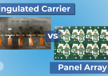
- Component Mounting: Components are attached using surface-mount technology (SMT) or through-hole technology. SMT is often performed in panel form to increase throughput, although this can lead to inefficiencies due to the necessity of removing defective (‘X’ out) boards.
- Soldering: Components are soldered to establish electrical connections.
- Testing: Each PCBA is tested to confirm its functionality.
FPCAs (Flexible Printed Circuit Assemblies):
Definition: Constructed from flexible materials like polyimide or polyester, FPCAs feature conductive traces that can bend or fold without impairing the circuit.
Applications: FPCAs are perfect for dynamic environments requiring flexibility and compact design, such as in smartphones, wearable technology, medical devices, and sophisticated automotive electronics.
Do you have more questions about Printed Circuit Boards (PCBA) and or Flex Circuit Board Assembly (FCBA) Assembly? Contact us today and speak to an engineer.
Manufacturing Process:
- Design: Specialized CAD software is used, taking into account the flexibility and bending stresses.
- Fabrication: Conductive traces are etched or printed on a flexible substrate.
- Component Mounting: Components are mounted using SMT, with each FPCA placed individually in carriers to maximize throughput and minimize concerns about defects.
- Encapsulation: A protective coating is applied to preserve flexibility and enhance durability.
- Testing: Each assembled FPCA undergoes tests to ensure it meets functionality and reliability standards.
Key Differences between PCBAs and FPCAs:
- Flexibility: FPCAs are inherently flexible, unlike the rigid PCBAs.
- Space Efficiency: FPCAs enable more compact designs, making them superior in space-constrained applications.
- Durability: The flexible nature of FPCAs makes them more resistant to vibrations and bending, ideal for dynamic applications.
- Cost: The specialized materials and manufacturing processes make FPCAs generally more expensive than PCBAs.
- Targeted Applications: The choice between PCBA and FPCA should be guided by the specific needs for flexibility, space constraints, and environmental resilience.
Conclusion: Both PCBAs and FPCAs serve critical roles in electronic manufacturing, but their usage depends greatly on the application’s specific requirements. PCBAs offer robustness and cost efficiency for traditional uses, whereas FPCAs provide indispensable flexibility and compactness for innovative, mobile designs. Understanding these distinctions helps in choosing the right circuit assembly for any given electronic device challenge.
Contact us with any questions about PCBAs or FPCAs.