Designing Rigid-Flex Circuits: What Engineers Need to Know
Lucia Zhao2025-07-08T16:05:14+00:00Rigid-flex PCBs combine the best of both worlds—the durability of rigid boards and the versatility of flexible circuits—into a single integrated solution. They’re ideal for compact, high-reliability applications where connectors and wiring harnesses would add too much bulk or risk.
But rigid-flex design isn’t just about stacking rigid and flex layers together. It requires careful planning across mechanical layout, layer stackups, bend dynamics, and manufacturing constraints.
Here’s what you need to know to get your rigid-flex design right the first time.
Why Choose Rigid Flex?
Rigid-flex circuits are commonly used in:
• Wearables and medical devices
• Avionics and aerospace systems
• Defense electronics
• Cameras and consumer electronics
• Test and measurement equipment
They’re especially beneficial when you need:
• Fewer connectors (increased reliability)
• Compact form factors with 3D packaging
• Reduced wiring or cable assembly steps
• Consistent signal routing across rigid and flex regions
Key Considerations in Rigid-Flex Design
1. Define the Mechanical Envelope First
Rigid-flex circuits are often designed to fit into a 3D space—so mechanical layout drives everything.
• Identify fold lines, bending zones, and fixed areas early.
• Ensure the flex sections are long enough to bend without excessive stress.
• Consider installation sequence: Will it be folded before or after assembly?
Tip: Avoid placing components near bend areas, even on the rigid side—bending can still introduce mechanical strain.
2. Plan the Stackup Carefully
Rigid-flex boards typically have different stackups in rigid and flex zones. The flex section might be only 1–2 layers, while the rigid areas may include multiple copper layers, ground planes, or power cores.
• Avoid unnecessary copper in bend regions.
• Use adhesiveless polyimide for better reliability and thinner profile.
• Include coverlay or flex solder mask for mechanical protection.
Note: Flex sections should maintain a minimum bend radius (usually ≥10× circuit thickness for dynamic applications, ≥6× for static folds).
Combine flexibility and durability in one seamless solution. Explore how PICA’s rigid-flex PCBs can reduce interconnects, improve reliability, and optimize your product’s footprint.
3. Add Stiffeners Where Needed
Stiffeners are added under connectors or component areas to:
• Prevent flexing during mating/unmalting
• Improve assembly handling
• Maintain planarity for soldering
Common stiffener materials include FR4, polyimide, or stainless steel. We can help determine the right thickness and material based on your component and assembly needs.

4. Manage Transitions Between Rigid and Flex
The rigid-to-flex transition is a critical stress point. Best practices include:
• Use tear stops or radius cutouts to prevent delamination.
• Keep copper away from the exact edge of the flex zone—offset by at least 0.030″.
• Allow room for strain relief fillets or adhesives if needed.
5. Watch for Common Pitfalls
• Vias in flex areas: These should be avoided unless specially designed; plated-through vias may crack during bending.
• Sharp copper corners: Avoid 90° corners on traces—use 45° or arcs to reduce stress risers.
• Poor layer symmetry: Asymmetrical stackups can cause warping during lamination.

• Overly aggressive bends: Short flex tails may delaminate or crack over time.
Assembly and Manufacturing Tips
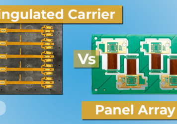
• Use panel rails and tooling holes for consistent placement and alignment.
• Indicate fold lines clearly on the drawing or gerber/mechanical layer.
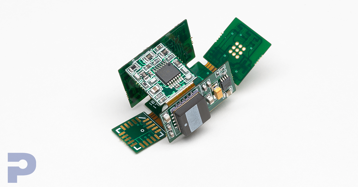
• Communicate final folded shape with 3D models or folding diagrams.
• Consider whether you want the boards shipped flat or pre-folded.
Pro Tip: PICA can review your 3D fold and propose modifications to reduce stress or improve fit before you lock the design.
Final Thoughts
Rigid-flex circuits offer unmatched design freedom and reliability—but they require tight coordination between mechanical, electrical, and manufacturing teams. The earlier we’re brought into the design process, the more we can help optimize stackups, transitions, and fabrication details to avoid costly mistakes.
At PICA Manufacturing Solutions, we support rigid-flex development from concept to production, helping you build smarter, more compact systems with fewer failure points.
Let us help you bring your next rigid-flex design to life—seamlessly and reliably.