Optimizing Design for Flexible Circuits: Best Practices and Considerations
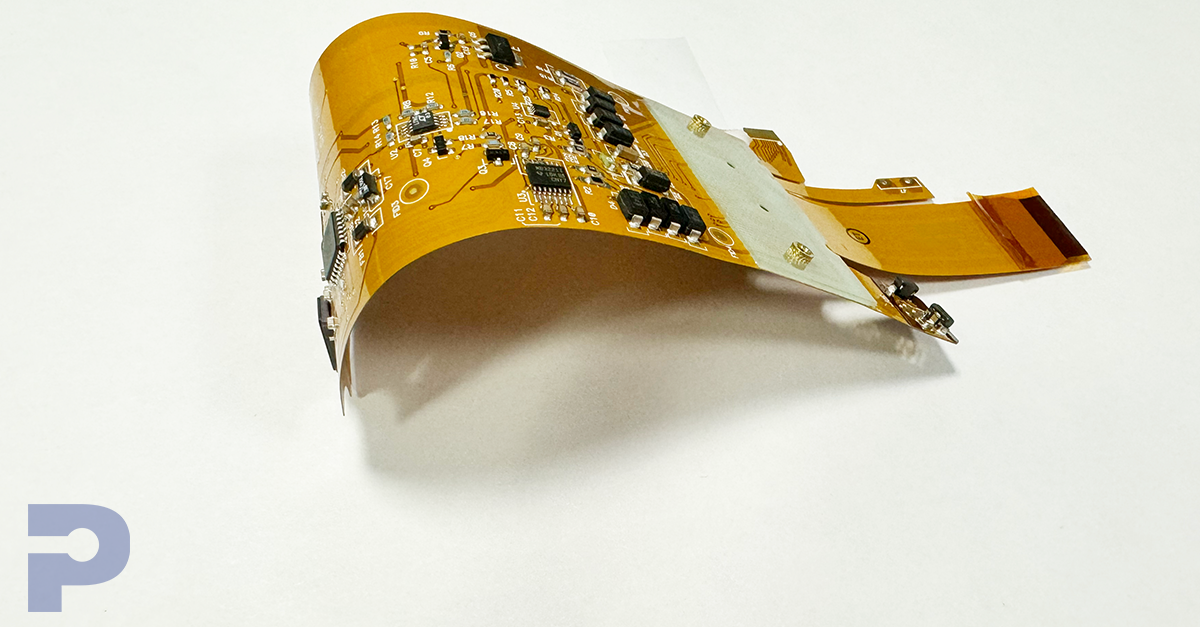
FlexPros2025-07-24T17:03:38+00:00Flexible circuits are essential in today’s compact, lightweight devices—thanks to their ability to bend, twist, and conform to tight spaces. But designing them for reliability and performance takes more than just a flexible substrate. At PICA Manufacturing Solutions, we specialize in helping engineers navigate the unique challenges of flex design to ensure durability and efficiency.
Want expert tips on designing better flexible circuits?
Watch our video to learn best practices and avoid common pitfalls: Watch Now
In this part 1, we’ll share design practices mastered through years of experience. These recommendations are specifically crafted to help designers and engineers create flexible circuits that can withstand the rigors of use without compromising functionality. Whether you’re developing for consumer electronics, automotive applications, aerospace, or medical devices, following these guidelines will enhance the robustness and reliability of your flexible circuit designs.
- Conductor Placement and Strain Minimization
One of the most critical aspects of designing flexible circuits is the placement of conductors. To minimize the strain on traces during flexing, it’s advisable to position the conductors along the center or neutral axis of the flex. This strategic placement reduces both compressive and tensile strains caused by bending, enhancing the circuit’s longevity and reliability.
- Managing Conductor Strain in Bend Areas
To best manage mechanical stress, ground planes, which can withstand tensile strain better than compression, should ideally be located on the outside of bends. This placement allows conductors, which are more vulnerable to tensile strain, to be positioned on the inside where they experience compression. Such an arrangement significantly helps in mitigating the risk of trace fractures under repeated flexing scenarios. Additionally, the bend region should be free of any plated-through holes, solder pads, or abrupt changes in conductor width, as these elements can become focal points for stress and potentially lead to circuit failure.
- Avoiding “I” Beam Configurations
In double-sided circuits, it is crucial to avoid routing conductors directly above one another in what is known as an “I” Beam configuration. This setup concentrates strain on the conductors during bending. To circumvent this issue, stagger the conductors on opposite sides of the circuit. This simple adjustment can significantly reduce the mechanical stress on the traces during flexing.
Explore our company profile
Explore PICA Manufacturing Solutions’ history, values, locations, and product offerings. Learn about our quality-first approach and engineering expertise.
- Optimizing Bend Radius
The bend radius is a pivotal design parameter that can greatly influence the flexibility and endurance of the circuit. Increasing the bend radius not only enhances the flexibility but also significantly extends the life of the circuit by reducing stress on conductors in the bend area. It’s essential to maximize the bend radius to prevent any conductor strains. Single-sided constructions are particularly recommended for dynamic applications due to their inherent flexibility and durability under repeated flexing. Here are some guidelines based on the type of circuit:
- Single-sided circuits: Maintain a bend radius of 3 to 6 times the circuit thickness.
- Double-sided circuits: A bend radius of 6 to 10 times the circuit thickness is recommended.
- Multilayer circuits: Opt for a bend radius of 10 to 15 times the circuit thickness.
- Dynamic applications: Consider a bend radius of 20 to 40 times the circuit thickness.
These guidelines help ensure that your flexible circuits maintain optimal performance and longevity, especially in applications where flexibility and durability are critical.
- Dynamic and Static Applications
For circuits that will be subjected to frequent and repetitive movements (dynamic applications), using materials and designs that accommodate higher strains without degradation is crucial. Conversely, for static applications, where the circuit flexes once or twice during installation and then remains stationary, the design can focus more on optimizing space and electrical performance.
Conclusion
Designing flexible circuits demands a comprehensive understanding of mechanical and electrical engineering principles to ensure performance and durability. By adhering to the outlined design practices—such as optimal conductor placement, managing bend areas, avoiding risky configurations, and adjusting the bend radius—you can enhance the robustness and reliability of your flexible circuit designs. Tailor these recommendations to the specific requirements of your application to achieve the best results.
Stay tuned for Part 2 of our series, where we will delve into additional critical aspects such as strain relief, tear resistance, and the impacts of vibration and shock. We’ll also explore the importance of incorporating filleting pads, using fiducials for precise assembly, and adhering to strict tolerances to further enhance the functionality and durability of flexible circuits.

